
In this tutorial you will learn how to code a sunburst effect inside a shader, using scanlines and polar coordinates. You will learn how to code the effect using the web based shader editor called Shadertoy.
Introduction
The sunburst effect is often used as a cool looking background. It can be coded or made in an image editor program. In the GIMP image editor, the scanlines are called blinds.
Here is a a nice video showing how to create the sunburst effect in the GIMP image editor using blinds and polar coordinates. But for this tutorial we will make this effect in a shader.
New Shader
To start, go to the Shadertoy website here. Then click on ‘New’. You should be greeted with a video window and code editor.
Constants
First define some constants at the top of the code editor, starting with the value for the mathematical constant ‘PI’.
// Math constants
const float PI = 3.14159265359;
const float TWO_PI = PI * 2.0;
Next define two constants for the colour of the sunburst effect.
// Colours
const vec3 COL1 = vec3(0.34, 0.58, 0.18);
const vec3 COL2 = vec3(0.28, 0.09, 0.44);
Now create three constants for customising the scanlines.
// Scanline constants
const float REPEAT = 30.0;
const float MOD_VALUE = 2.0;
const float ROTATION_SPEED = 0.02;
The ‘REPEAT’ value will define how many scanlines there are. The ‘MOD_VALUE’ will define the size of the gap between the scanlines. And the ‘ROTATION_SPEED’ will control how fast the sunburst effect rotates.
atan2
Next we need to define an arctangent 2 function, since the GLSL programming language doesn’t have this function. So we will use this one from Stack Overflow.
// GLSL atan2 function
// https://stackoverflow.com/questions/26070410/robust-atany-x-on-glsl-for-converting-xy-coordinate-to-angle
float atan2(in float y, in float x)
{
    bool s = (abs(x) > abs(y));
    return mix(PI/2.0 - atan(x,y), atan(y,x), s);
}
Polar Coordinates
Now we need a function which converts a cartesian position to polar coordinates. We will use this one from Ronja’s website:
// Convert to polar coordinates
// https://www.ronja-tutorials.com/post/053-polar-coordinates/
vec2 ToPolar(vec2 cartesian)
{
	float len = length(cartesian);
	float angle = atan2(cartesian.y, cartesian.x);
	return vec2(angle / TWO_PI, len);
}
Notice how it uses the atan2 function we defined earlier.
The function returns the angle and the distance from the cartesian position. The angle is returned in the range of -0.5 to 0.5. This will be useful later.
Scanlines
Finally we need one more function for creating the scanlines.
// Create scanlines
// https://agatedragon.blog/2024/01/26/shadertoy-scanline/
float Scanlines(float x, float repeat, float modValue)
{
    x = floor(x * repeat);
    return mod(x, modValue);
}
For more information on the scanlines, check out my tutorial here.
Essentially we are creating a continuous pattern of lines in alternating colours. As you can see in the image below with the black and white lines.
Main Function
Now we have everything we need and can start coding inside the main function.
void mainImage(out vec4 fragColor, in vec2 fragCoord)
{
    // Code goes here
}
So first lets create the texture coordinates. Which will be defined in the 0 to 1 range.
    // Normalised pixel coordinates (from 0 to 1)
    vec2 uv = fragCoord / iResolution.xy;
Next we will create a position variable using the texture coordinates and subtract 0.5 from it. This will change the number range from 0 to 1, to -0.5 to 0.5. Which means 0 is now the centre of the screen.
    // Convert to polar coordinates
    vec2 pos = uv - 0.5;
Now we can convert our position variable to polar coordinates. This will get us the angle and distance from our cartesian position.
pos = ToPolar(pos);Next lets create the scanlines using our position variable. We are using the ‘x’ component of the position variable here. Remember that the ‘x’ represents the angle, and it is in the -0.5 to 0.5 range.
We add time and rotation speed to make the scanlines rotate. We also use the repeat and mod value from earlier.
    // Create scanlines
    float scanlines = Scanlines(pos.x + (iTime * ROTATION_SPEED), REPEAT, MOD_VALUE);
To see what our scanlines look like, we can output the scanlines value to the pixel fragment colour.
    // Black and white scanlines
    fragColor = vec4(vec3(scanlines), 1.0);
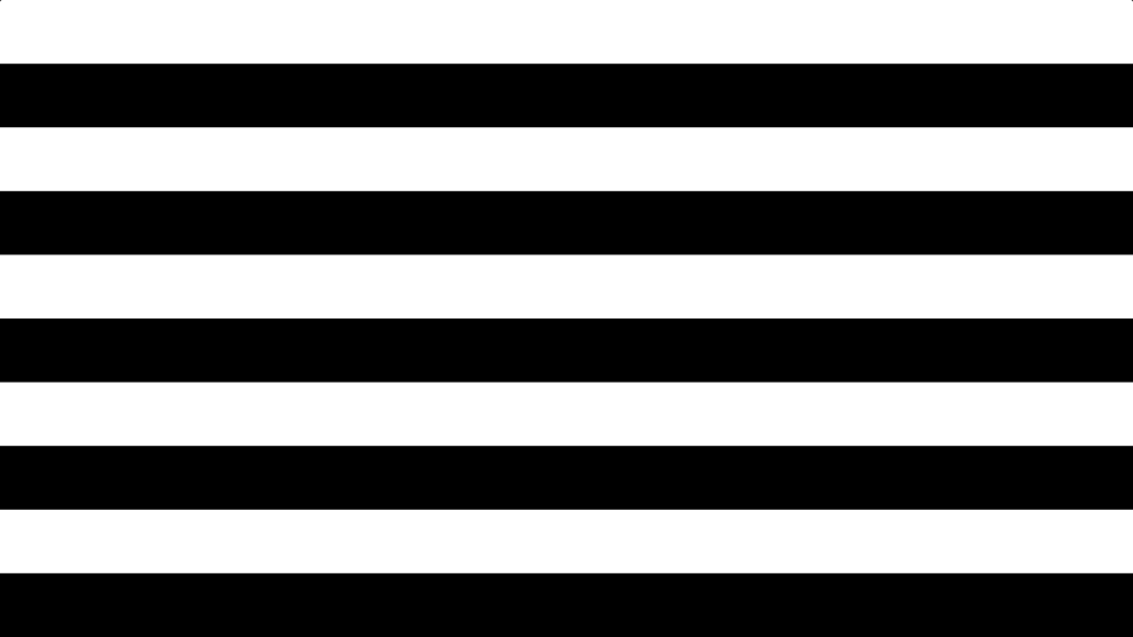
We can also see what our scanlines look like before the polar coordinates are applied by using the ‘uv’ variable instead of the position variable, like so:
float scanlines = Scanlines(uv.x + (iTime * ROTATION_SPEED), REPEAT, MOD_VALUE);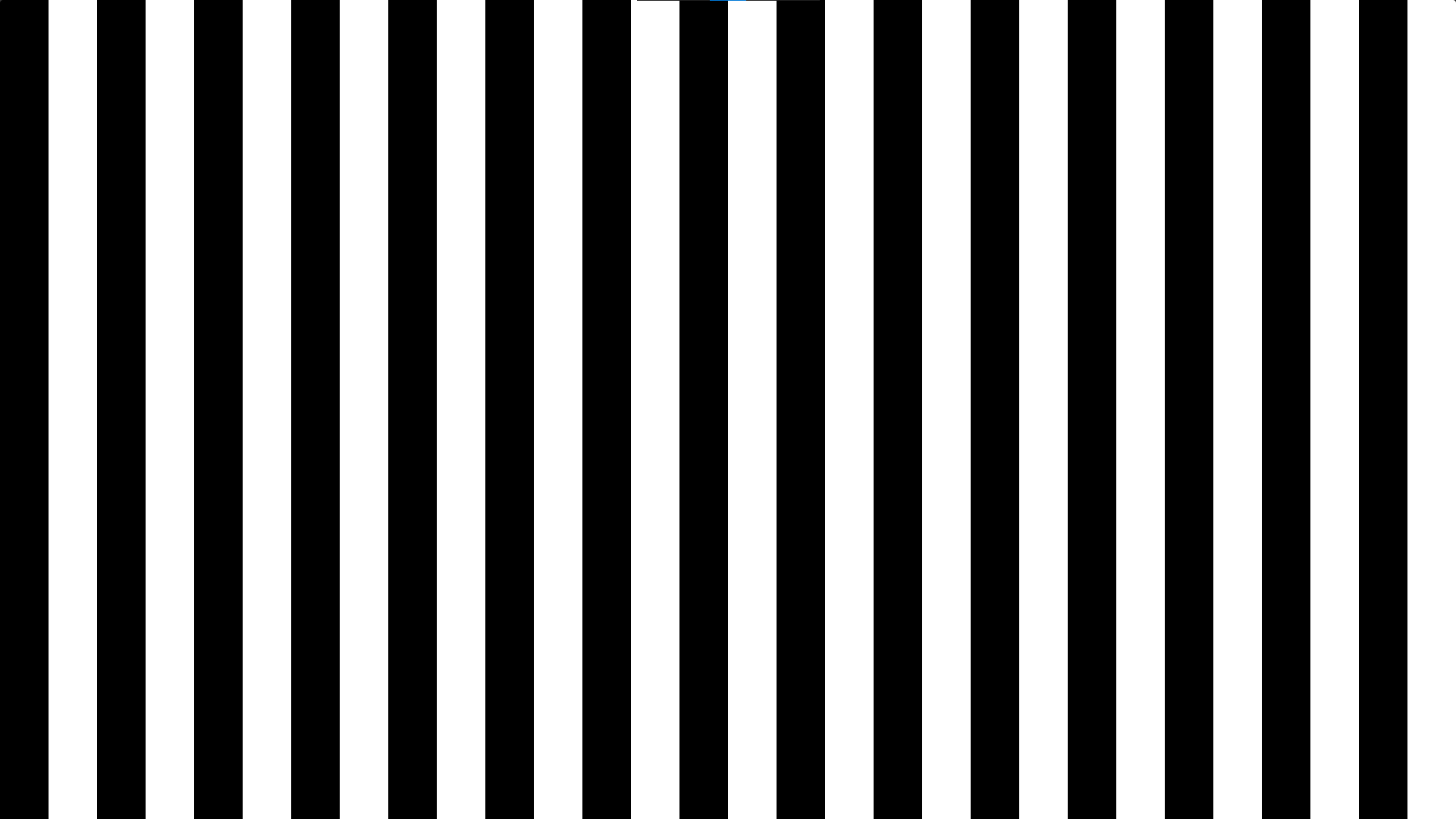
Finally to change the colour of the sunburst effect we use the mix function by plugging in the scanlines value to control which colour is displayed:
    // Change colour of the scanlines
    fragColor.rgb = mix(COL1, COL2, scanlines);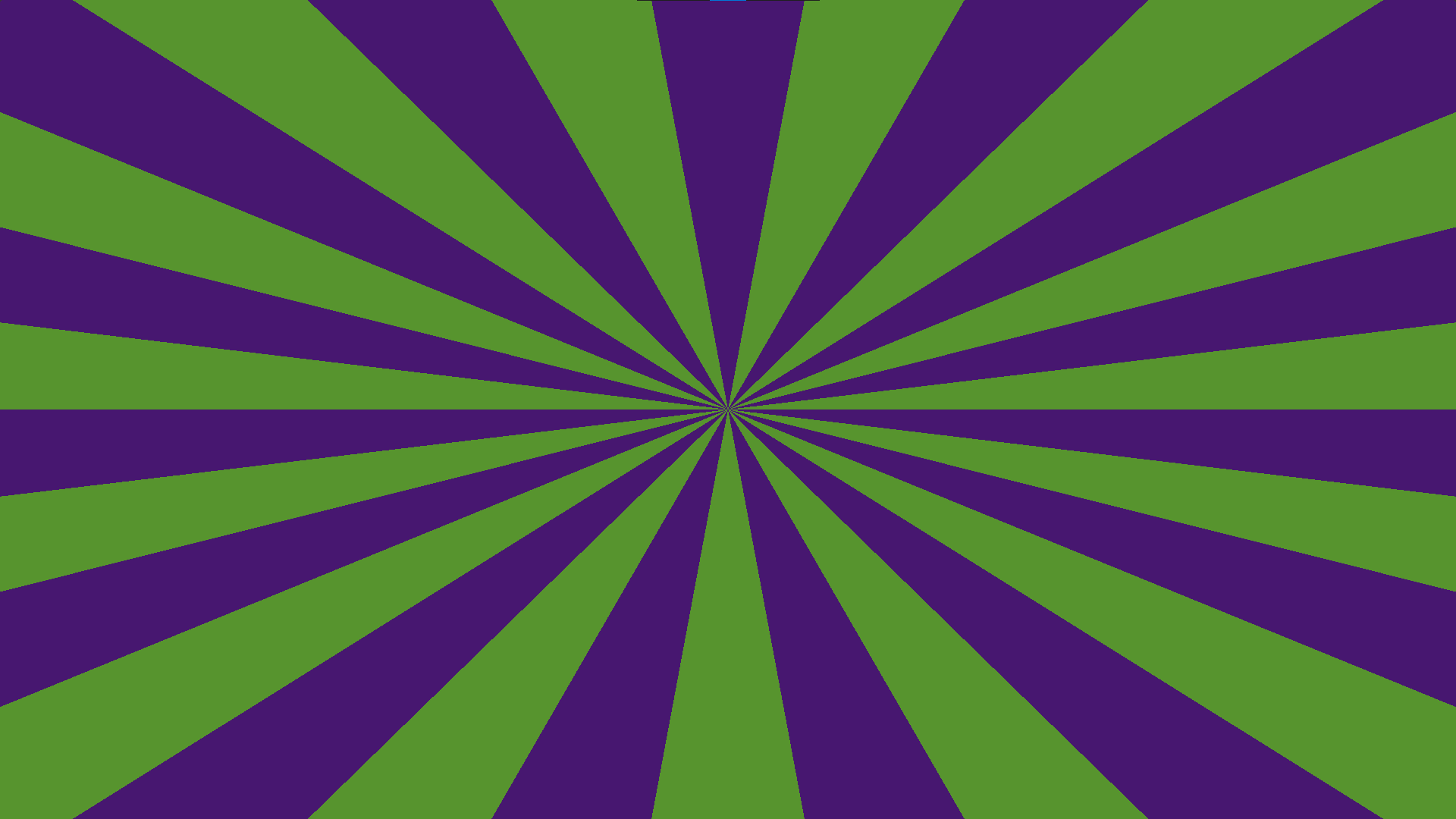
Demo
You can see a complete demo of the sunburst effect on Shadertoy here.
Repeating Circles
Alternatively, if you don’t want to create a sunburst effect, you can create this cool repeating circle pattern. By using the distance value when creating the scanlines. The distance value is the ‘y’ component of the position variable.
float scanlines = Scanlines(pos.y + (iTime * ROTATION_SPEED), REPEAT, MOD_VALUE);
Conclusion
Thanks for reading this tutorial, I hope you enjoyed it and learned how easy it is to create a sunburst effect using scanlines and polar coordinates.
For more shader coding tutorials, check out my shaders page here.
